
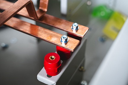
Bolted Busbar with red insulated support bar
In electrical power distribution, a busbar is a thick strip or bar of copper or aluminum that conducts electricity within a switchboard, distribution board, substation, or other electrical apparatus. Busbars are used to carry very large currents or to distribute current to multiple devices within switchgear or equipment.
For example, a household circuit breaker panel board will have bus bars behind the back panel, arranged with protruding connection points for the connection of multiple branch circuit breakers. An aluminum smelter will have very large bus bars used to carry tens of thousands of amperes to the electrochemical cells that smelt aluminum from alumina ore.
For very large currents, where it is difficult to provide circuit protection, an isolated-phase bus is used. Each phase of the circuit is run in a separate grounded metal enclosure. The only fault possible, barring a catastrophic physical event, is a phase-to-ground fault since the enclosures are separated. This type of bus can be rated up to 50,000 amperes and up to hundreds of kilovolts (during normal service, not just for faults), but is not used for building wiring in the conventional sense.
A conductor’s ability to carry current (how much it can carry) is dependent, partly, on the cross-sectional area of the conductor and partly on the material of the conductor. A bus provides a proportionally larger cross section than the standard insulated conductors that could be fitted into the same space. This is partly due to the space that insulation occupies.
Most busbars are not insulated along their length. This is possible because they are rigidly mounted on insulation ‘stand-offs’ and use air as the insulating medium along the length. Connections between lengths of busbar are soldered/welded for smaller sizes, but often bolted on larger bars. With the rigidity of the bar itself, and the rigid mounting, this allows for connections to be made by clamping around the bar.
There is no symbol for busbars. It is shown on diagrams as a conductor but may have a note that identifies it.
Here are pictures of two types of busbars. There are many, many others.
Bolted Busbar with red insulated support bar
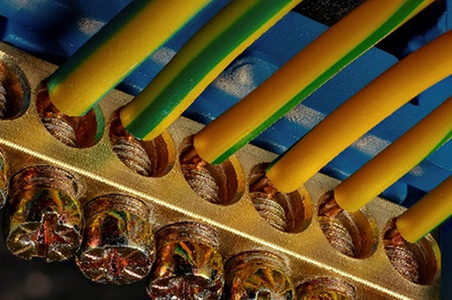
Circuit Breaker box ground or neutral buss
Busbars can be found anywhere but are usually inside other electrical cabinets or structures. In some very old installations, you may encounter an exposed bus, but the area should be restricted to be compliant with current regulations.
Bus failures usually occur at joints, connections, and insulated ‘stand-offs.’ Bolts loosen, and welded joints break, sometimes with only a hairline crack. Stand-offs crack or crumble but may also develop tracking if carbon deposits on the surface provide a current path. Almost all bus failures are due to excessive heat. Good electrical conductors are also usually good heat conductors.
A single bad connection can cause the joint to overheat, causing bolts to stretch and torque to be reduced, causing more overheating. Heat deteriorates stand-off insulators and results in the expansion and contraction of the bar itself, resulting in breaks or cracks. In extreme cases, the bar can buckle or sag. Isolated buses can fail due to loss or contamination of isolation or insulation media. Gas-filled enclosures must be checked for integrity, gas leakage, gas volume, and contamination.
Keep in mind that in addition to its electrical integrity, older gear may also have issues with safety, particularly regarding arc flash exposures.
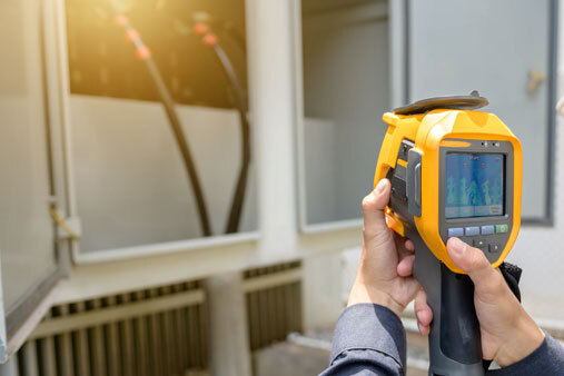
Visual inspections are critical to discover physical damage. Infrared inspections can show severe cracks, and hot spots or connection issues.
Ultrasonic testing may reveal arcing or corona at loose joints or invisible cracks. Ultrasound testing is a means for detecting the possibility for arc flash events. When a hand-held ultrasonic device is utilized to scan enclosed electrical equipment, the process is immediate, precise, and straightforward. With experienced technicians, immediate results can be obtained allowing for instant decisions. It will help inspectors by reducing the need to wear cumbersome, unpleasant personal protective equipment during their initial electrical inspection.
Isolated-Phase Busses require additional inspections in accordance with manufacturers’ recommendations. They are complicated assets, requiring both PdM (like other bus runs), as well as regular maintenance. Some are cooled, while some enclosures are filled with gas. Gas-filled buses must be considered an 'active' asset for maintenance purposes. Other buses and bus enclosures should be considered assets.
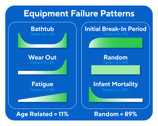
The life of most busbars are designed to be very rugged; they are still subject to normal physical effects of environments or abuse. In addition, the components are all subject to random or age-related failures, per the ‘bathtub’ curves shown below.
Life expectancy of the bus itself is very long. It could well be 30 years or more, depending on proper maintenance, timely repair, electrical loading, manufacturer, and installation environmental factors. This may vary significantly between manufacturers but is a sufficient baseline. However, most clients will not see this length due to overhauls, retrofits, and upgrades.
Allied Reliability provides asset management consulting and predictive maintenance solutions across the lifecycle of your production assets to deliver required throughput at lowest operating cost while managing asset risk. We do this by partnering with our clients, applying our proven asset management methodology, and leveraging decades of practitioner experience across more verticals than any other provider. Our asset management solutions include Consulting & Training, Condition-based Maintenance, Industrial Staffing, Electrical Services, and Machine Reliability.
Receive the latest insights on reliability, maintenance, and asset management best practices.