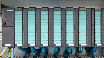
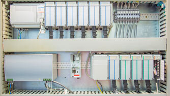
Siemens S7-300 system in a rack. From left-to-right: power supply unit & CPU, digital input modules, and digital output modules.
A programmable logic controller (PLC), or programmable controller, is an industrial digital computer that has been made very robust and modified for the control of manufacturing processes, such as robotic device assembly lines, or any activity that requires ease of programming, high reliability, and process fault diagnosis. PLCs were first developed in the automobile industry to provide flexible, ruggedized, and easily programmable controllers to replace hard-wired relays and timers. Since then, they have been widely adopted as highly reliable automation controllers suitable for harsh environments.
In my younger years as an Instrument Technician at an oil and gas facility, I once worked for days trying to locate the source of intermittent, random deletion of parts of the logic program. After replacing every module, and reloading the program, the same thing occurred repeatedly, but at a different place in the program. Finally, I found metallic dust from a recent cabinet modification deposited in the backplane terminal strips. Every time I replaced or reseated a module, the wedged metallic dust shifted, changing the results. From that point on, any work done in an area where PLCs were installed would require the application of a cover/enclosure (shop towel, cardboard box, etc.) over the PLC; then after the work has been completed, clean the enclosure and PLC area with a vacuum. Intermittent anomalies can be enormously frustrating. Do you have a PLC in your facility that is never seen or heard from, stashed away inside a cabinet to never be dealt with again until the next presidential election?
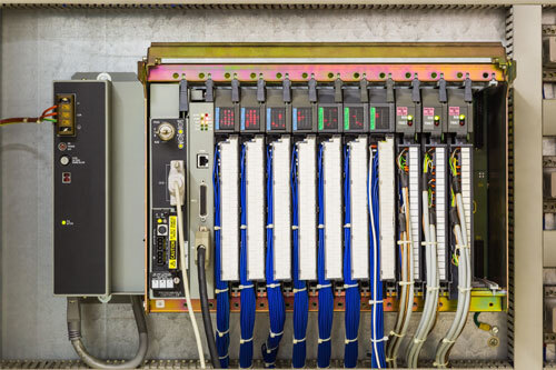
PLC for a monitoring system in the oil and gas industry.
Source: iStock, By Getty Images
PLC control systems are the heart of any production facility, yet it is often the most forgotten and under-appreciated system. Without a reliable PLC source in place, operations of any production facility would not be possible. In spite of the critical nature of the PLC, regularly scheduled maintenance is not always a primary focus in some facilities. A great way to keep PLCs in good standing is to avoid unplanned downtime and maximize the cost of ownership by predicting problems before they occur and tackling them in a timely manner.
Preventive maintenance relies on good data collection, such as mean time to repair and mean time to failure. While this helps to prevent unexpected shutdowns via early problem prediction/detection, the one disadvantage of preventive maintenance is that you can end up needlessly changing parts based on manufacturer guidelines. Utilizing a predictive maintenance method, however, can help you escape this issue.
Predictive maintenance, which also allows you to repair or replace equipment before it runs-to-failure, is effectively taking preventive maintenance a step further, by either physically using handheld devices or through electronic sensors. Then the Instrument Technician can detect and confirm when machines need repair. The value of predictive maintenance over preventive maintenance is that you have clear indicators and real-time data, such as sensory, vibration, and temperature abnormalities, to reveal that the PLC does indeed require maintenance. Do you have a preventive or predictive maintenance plan in place?
Neglecting the maintenance of the PLC over a long period of time will inevitably lead to costly emergency repairs and equipment failures, in addition to elevated safety and property risks. Downtime is extremely costly, and not only can it seriously affect plant output, with the recent advances in PLC technology that embrace safety-related functions, it can occasionally create a hazardous situation that needs immediate attention. The key is to be well educated and use preventive maintenance checklists to keep your PLC systems in good working order.
A PLC is a hard-wired, real-time system that produces output results in response to input conditions within a limited time, to prevent unintended operations from occurring. The main difference from most other computing devices is that PLCs are intended for and, therefore, tolerant of, more severe conditions (such as dust, moisture, heat, and cold), while offering extensive input/output (I/O) to connect the PLC to sensors and actuators. PLC input can include simple digital elements, such as limit switches, analog variables from process sensors (such as temperature and pressure), and more complex data (e.g. from positioning or machine vision systems). PLC outputs can include elements like indicator lamps, sirens, electric motors, pneumatic or hydraulic cylinders, magnetic relays, solenoids, or analog outputs. The input/output arrangements may be built into a simple PLC, or the PLC may have external I/O modules attached to a computer network that plugs into the PLC.
PLCs range from small ‘building brick’ devices with tens of I/O’s in a housing integral with the processor, to large rack-mounted modular devices with hundreds of I/O’s, and which are often networked to other PLC and SCADA systems. They can be designed for multiple arrangements of digital and analog I/O’s, extended temperature ranges, immunity to electrical noise, and resistance to vibration and impact. Programs to control machine operation are typically stored in battery-backed-up or non-volatile memory.
The PLC was developed with several key attributes in mind, e.g. to tolerate the process environment, to support input and output in an easily extensible manner, not require years of training to use, and permit its operation to be monitored. Since many industrial processes have timescales easily addressed by millisecond response times, modern (fast, small, reliable) electronics greatly facilitate building reliable controllers, with performance traded off for reliability.
Initially, PLCs were designed to replace relay logic systems. These PLCs were programmed in ladder logic, which strongly resembles a schematic diagram of relay logic. This program notation was chosen to reduce training demands for the existing technicians. Other early PLCs used a form of instruction list programming, based on a stack-based logic solver.
Modern PLCs can be programmed in a variety of ways, from the relay-derived ladder logic to programming languages, such as specially adapted dialects of BASIC and C. Another method is state logic, a very high-level programming language designed to program PLCs based on state transition diagrams. Most PLC systems today adhere to the IEC 61131/3 control systems programming standard that defines five languages: Ladder Diagram (LD), Structured Text (ST), Function Block Diagram (FBD), Instruction List (IL), and Sequential Flow Chart (SFC).
Many early PLCs did not have accompanying programming terminals that were capable of graphical representation of the logic, so the logic was instead represented as a series of logic expressions in some version of Boolean format, based on Boolean algebra. As programming terminals evolved, it became more common for ladder logic to be used, for the aforementioned reasons and because it was a familiar format used in electromechanical control panels.
PLC functions have evolved over the years to include sequential relay control, motion control, process control, distributed control systems, and networking. The data handling, storage, processing power, and communication capabilities of some modern PLCs are approximately equivalent to desktop computers. PLC-like programming, combined with remote I/O hardware, allows a general-purpose desktop computer to overlap some PLCs in certain applications.
Desktop computer controllers have not been generally accepted in heavy industry because the desktop computer runs on less stable operating systems than PLCs, and because the desktop computer hardware is typically not designed to the same levels of tolerance with respect to temperature, humidity, vibration, and longevity as the processors used in PLCs. Operating systems, such as Windows, do not lend themselves to deterministic logic execution, with the result that the controller may not always respond to changes of input status with consistent timing as expected from PLCs. Desktop logic applications are used in less critical situations, such as laboratory automation and small facilities where the application is less demanding and critical, because they are generally much less expensive than PLCs.
Analog signals have continuously variable amplitudes like the sounds out of a speaker on a radio, with a range of values between zero and full-scale. These are typically interpreted as integer values (counts) by the PLC, with various ranges of accuracy depending on the device and the number of bits available to store the data. As PLCs typically use 16-bit signed binary processors, the integer values are limited to between -32,768 and +32,767. Pressure, temperature, flow, and weight are often represented by analog signals. Analog signals can use voltage or current with a magnitude proportional to the value of the process signal. For example, an analog 0 to 10 V or 4-20 mA input would be converted into an integer value of 0 to 32,767.
Current inputs are less sensitive to electrical noise (e.g. from welders or electric motor starts) than voltage inputs.
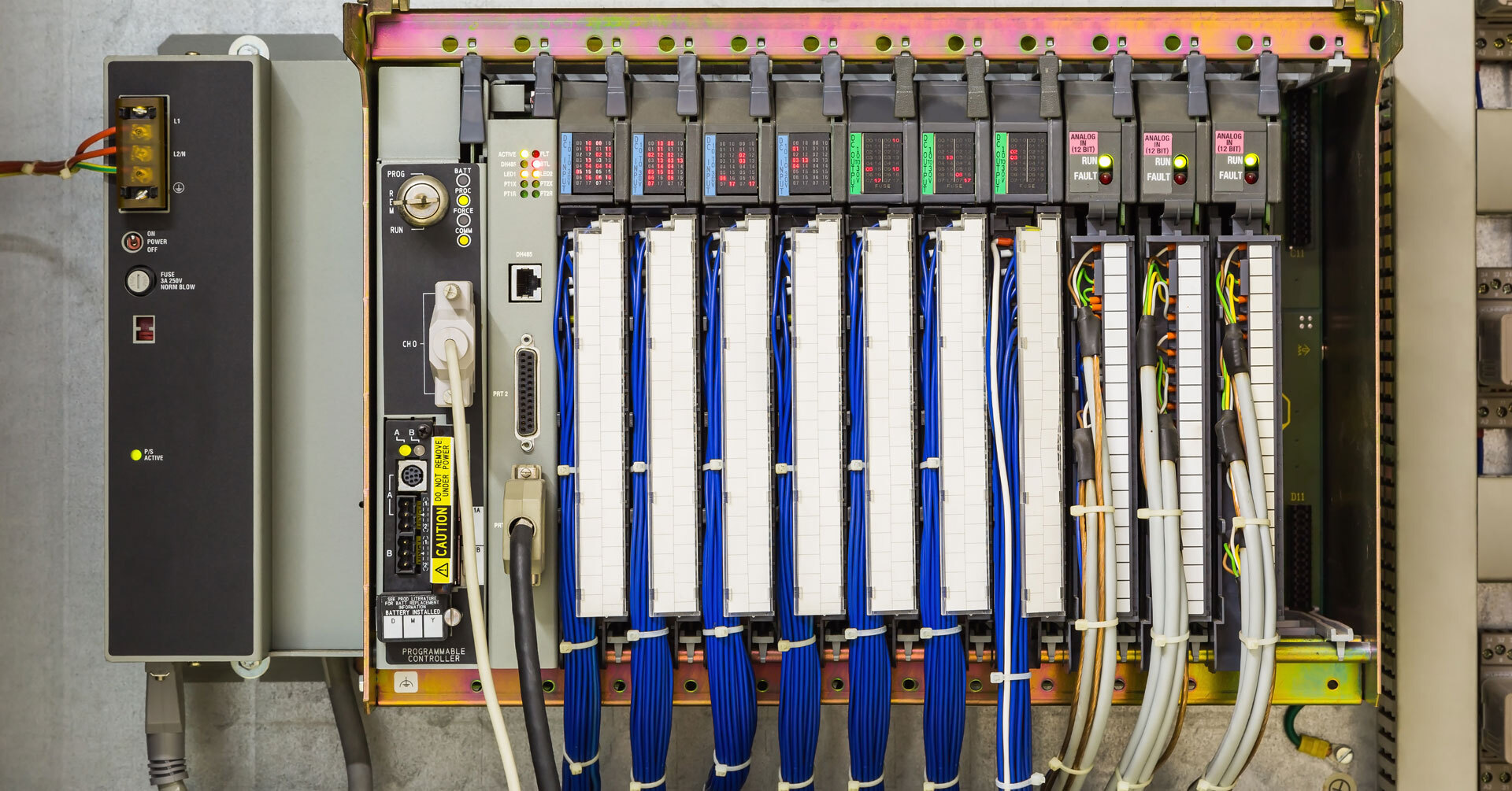
The appearance of PLCs varies by manufacturer, model, and application. Modules (or cards) usually include a central processing unit (CPU) or logic board, input and output cards (digital and/or analog), communications, and a power supply. Other modules may also be included, as needed by the application.
Siemens S7-300 system in a rack. From left-to-right: power supply unit & CPU, digital input modules, and digital output modules.
Allen-Bradley 500 PLC unit, consisting of separate elements. From left to right: power supply, CPU controller, and input/output modules.
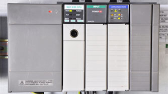
Allen-Bradley PLC installed in a control panel.
Source: iStock, By Getty Images
Although PLCs are designed to be rugged, they are still subject to normal physical effects of environments or abuse. In addition, the electronic components are all subject to random or age-related failures, per the ‘bathtub’ curves shown below.
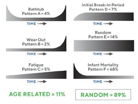
Source: RCM Failure Curves from Nowlan & Heap
Other than field device failure, power supply problems and I/O failures are the typical kinds of problems encountered. The main CPU controller, itself, has a non-rechargeable battery; its purpose is to provide the DC power necessary to retain the controller’s contents of the non-volatile memory in case power is lost from the PLC, either controlled or uncontrolled. The CPU program is lost after about 30 minutes if the battery is removed or is weak. The CPU controller batteries should be placed on a routine maintenance schedule (at least yearly) to avoid total program loss. Some CPU controller batteries are hot-swappable, and others are not (check the manufacturer’s CPU manual for reference). The plug-in modules may succumb to laminated contact problems or backplane damage. Output modules may include fused connections, which must be checked for looseness and fit.
Although random failures do occur, most PLCs are replaced or overhauled due to obsolete technology or unavailable parts, rather than life expectancy limits.
Whether or not PLCs are included in the equipment walk-down, they should be included as assets in the Master Asset List (MAL), also called the Master Equipment List (MEL). Where they are placed in the asset hierarchy will vary by company. Typically, the MAL is found in a computerized maintenance management system (CMMS), like SAP, Maximo, or another elementary system, like Excel. Depending on the age of the data, it may require review, and this should be done by performing an equipment walk-down.
The Master Equipment List should include the following:
The MEL is usually defined as part of an asset hierarchy. ISO 14224 defines equipment hierarchy levels, i.e. the hierarchy should be categorized to at least level 6, the asset level. Ideally, the equipment will be in a hierarchy that is documented to the component level. A well-developed asset hierarchy is necessary to identify equipment and should be compliant with the ISO 14224 standard diagram shown below.
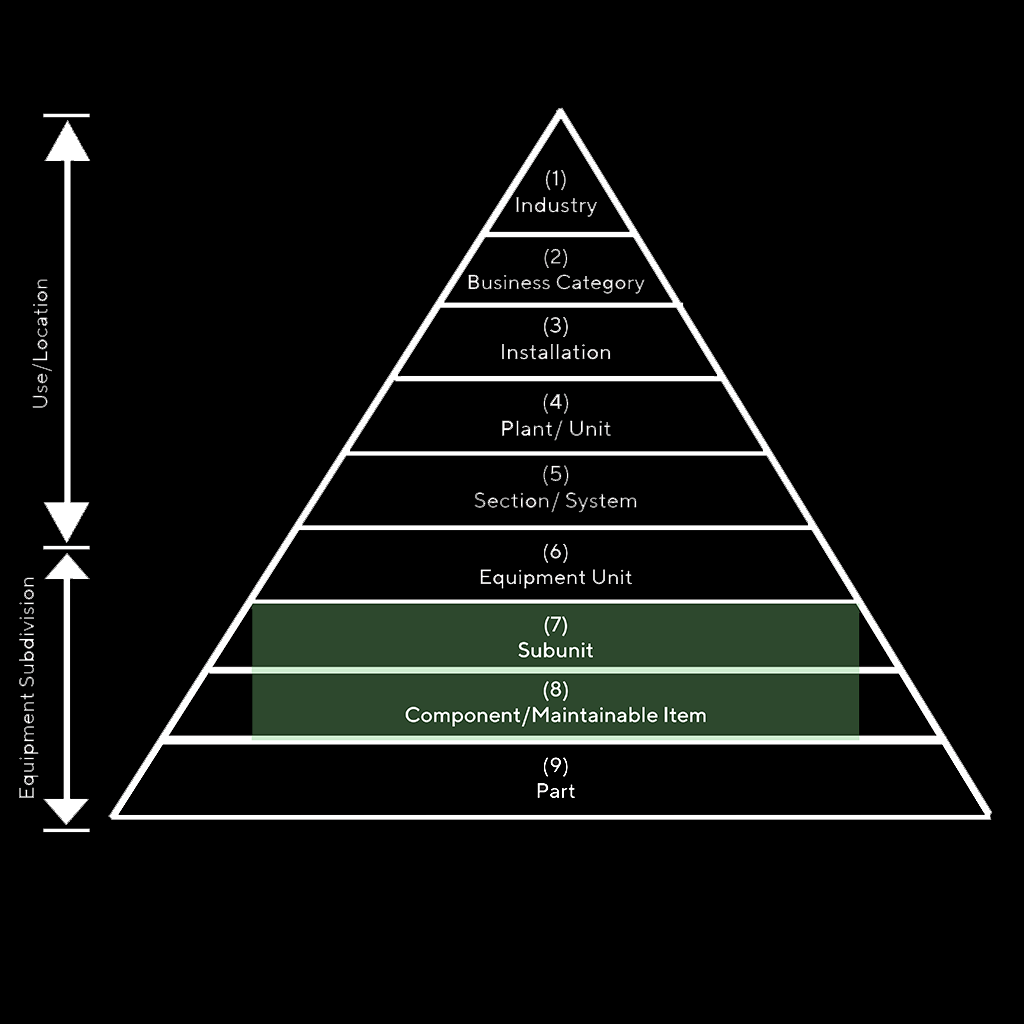
Source: International Standard ISO 14224 Third Edition 2016-09-15. Petroleum, petrochemical, and natural gas industries — Collection and exchange of reliability and maintenance data for equipment. https://www.iso.org/standard/64076.html
Hierarchies can be either location-based or system based, as shown in the below examples.
Location-based Hierarchy

System-based Hierarchy

| Level Number | Hierarchy Type | Example |
| 1 | Organization | 2000 - Company |
| 2 | Site | 776 - Biomass |
| 3 | Plant Area Process | 90000 - Pro Plex-T |
| 4 | System Process ID | XXXX |
| 5 | Functional Location | XXXX-CM or XXXX-DSC-11 |
| 6 | Instrument Functional Location or Loop | XXXX-PT-01 or XXXX-TC-02 (Loop) |
| 7 | Equipment | 6-digit non-intelligent number |
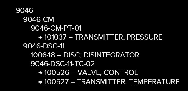
Key: Plant Area Process IDs
9046 - Dryer
9047 - Cooler
9048 - RTO
9049 - Packaging
9050 - Elect
Source: Allied Reliability
Note: If PLCs are in your equipment walk-down, remember that authorization may be required to open electrical cabinets. Therefore, craft escorts may be required to access anything beyond the most cursory information. Additional information should be available during a file search.
The following main steps should be followed as preventive maintenance to maximize the PLC’s life expectancy.

Finally, any software-driven device is subject to corruption or erasure. Strong area magnetization can cause unpredicted complications and unexpected process disruption. Therefore, take the following precautions:
In addition to providing a detailed explanation of PLCs in general, this educational blog has recommended several PLC maintenance guidelines to make sure the preventive maintenance of your PLCs best meet the needs of your company or organization. If you would like further guidance or support in improving or establishing better reliability for the electrical, electronic, or mechanical assets in your organization, please contact Allied Reliability. We would be pleased to help in your reliability journey.
The contributions made by the following people to this blog article are greatly appreciated: David Rempel, Reliability Professional, Allied Reliability; and Sam Cowan, CMRP, ARP-E, Technical Services Manager, C&T, Allied Reliability.
Allied Reliability provides asset management consulting and predictive maintenance solutions across the lifecycle of your production assets to deliver required throughput at lowest operating cost while managing asset risk. We do this by partnering with our clients, applying our proven asset management methodology, and leveraging decades of practitioner experience across more verticals than any other provider. Our asset management solutions include Consulting & Training, Condition-based Maintenance, Industrial Staffing, Electrical Services, and Machine Reliability.
Receive the latest insights on reliability, maintenance, and asset management best practices.